
Secure gripping and transfer
Vacuum cups and tooling can hold and move suitable workpieces when load and leakage are correctly assessed.
APPLICATIONS · MACHINERY & AUTOMATION
Vacuum gripping, machine holding and CNC clamping are sized from the workpiece, leakage, cycle time, safety factor, line loss and simultaneous demand.
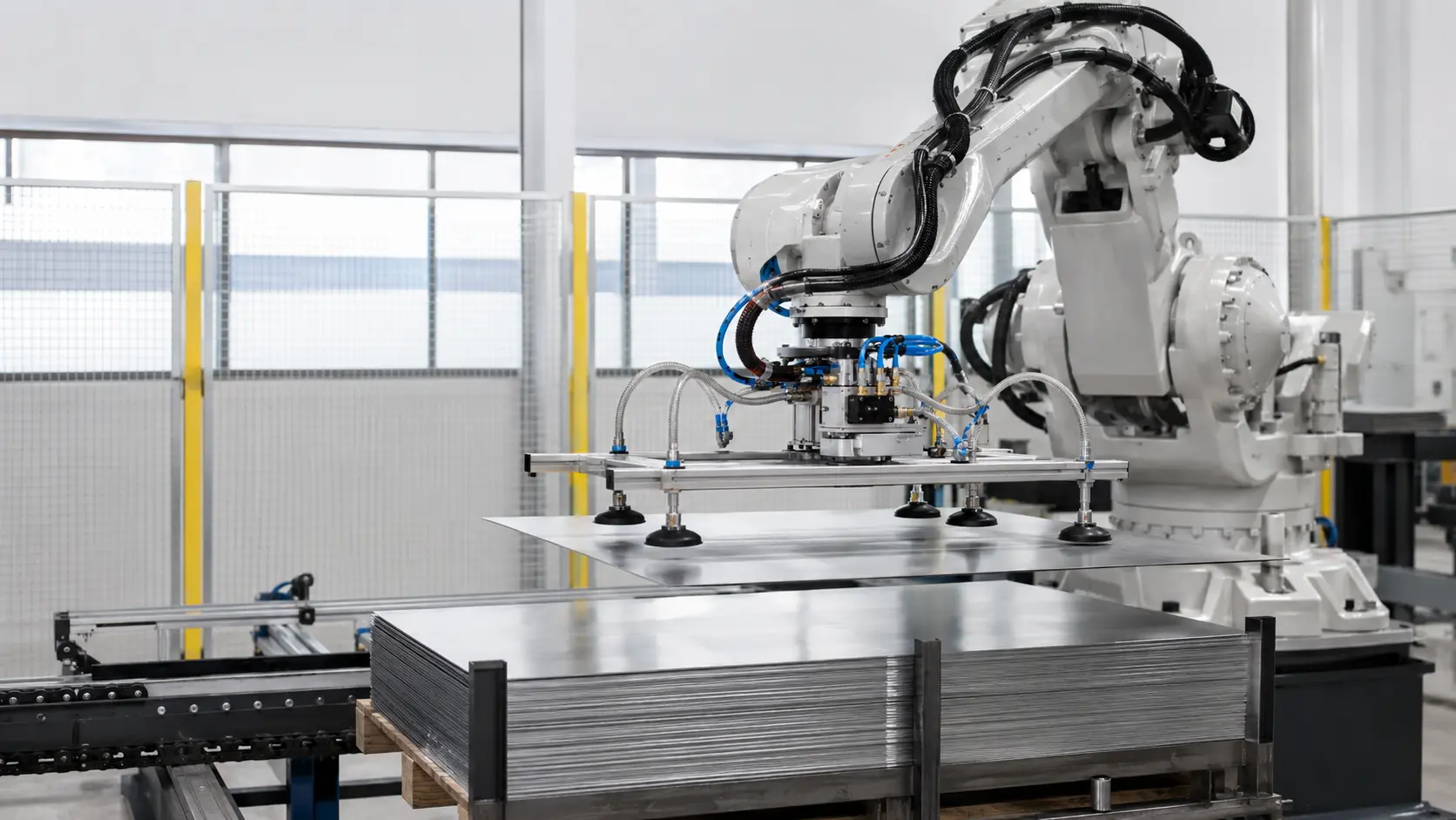
Workpiece surface, porosity and acceleration affect leakage and holding force. The vacuum source, buffer volume, valves and pipework must therefore be reviewed as one system.
Vacuum cups and tooling can hold and move suitable workpieces when load and leakage are correctly assessed.
A properly sized source supports repeatable vacuum holding during machining operations.
Correct line diameter, local storage and valve arrangement reduce avoidable response delay.
Multiple machines can share a managed vacuum network with zoning and duty/standby capacity.
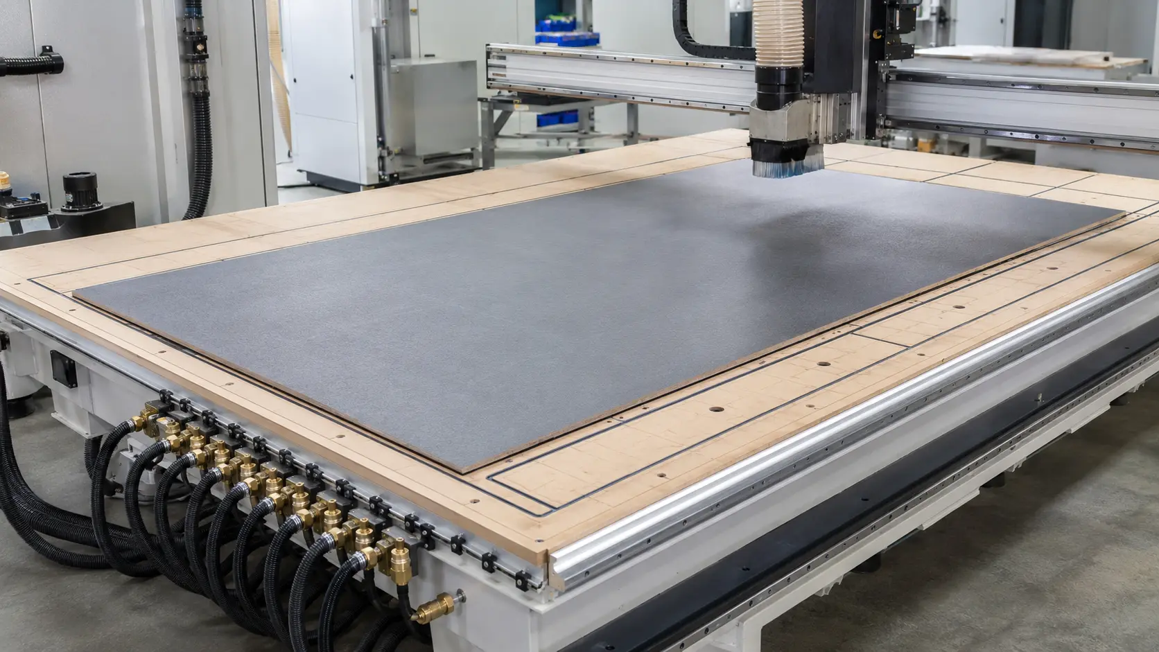
Effective area, surface leakage, cutting force and safety factor determine the required operating vacuum and capacity.
Four data groups establish the vacuum source and network arrangement.
Talk to Our Technical TeamDefine mass, dimensions, surface finish, porosity and the available sealing area.
Include acceleration, machining forces, orientation and the required safety factor.
Estimate system leakage and the time allowed to establish vacuum before movement or machining.
Simultaneous use, pipe length, zones, storage and redundancy define a local or central system.
The correct technology depends on required vacuum level, leakage, response time and operating pattern.
Published family ranges are indicative. Final selection must be checked at the actual operating pressure, gas or material load, temperature, duty cycle and installation conditions.
Reliable performance depends on the pump or blower, protection equipment, line arrangement, controls and the real process operating point.
Capacity and pressure are checked together at the actual inlet conditions and duty cycle.
Share Operating DataFilters, separators, condensers, receivers and valves are selected around moisture, particles, liquid carry-over and process risk.
Review the Process LoadPipework, controls, isolation, accessibility and redundancy are included in the final system architecture.
Explore Blowers & PumpsSend the workpiece, holding area, motion or cutting load, leakage, cycle time, machine count and pipe layout so we can define the vacuum source.