CUSTOM ENGINEERING · REFERENCE PROJECTS

Custom-Engineered Vacuum Systems

For applications where standard product configurations are not sufficient, we engineer vacuum chambers, vessels and auxiliary systems around the required volume, connection layout and process conditions.

Process-specific engineeringVacuum chambers and vesselsPump and vacuum-line integration
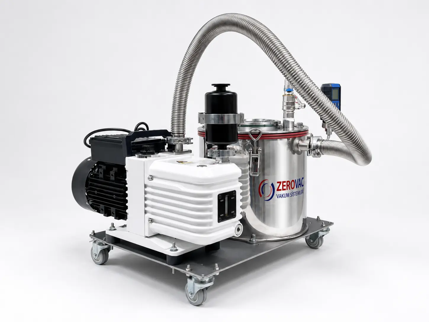
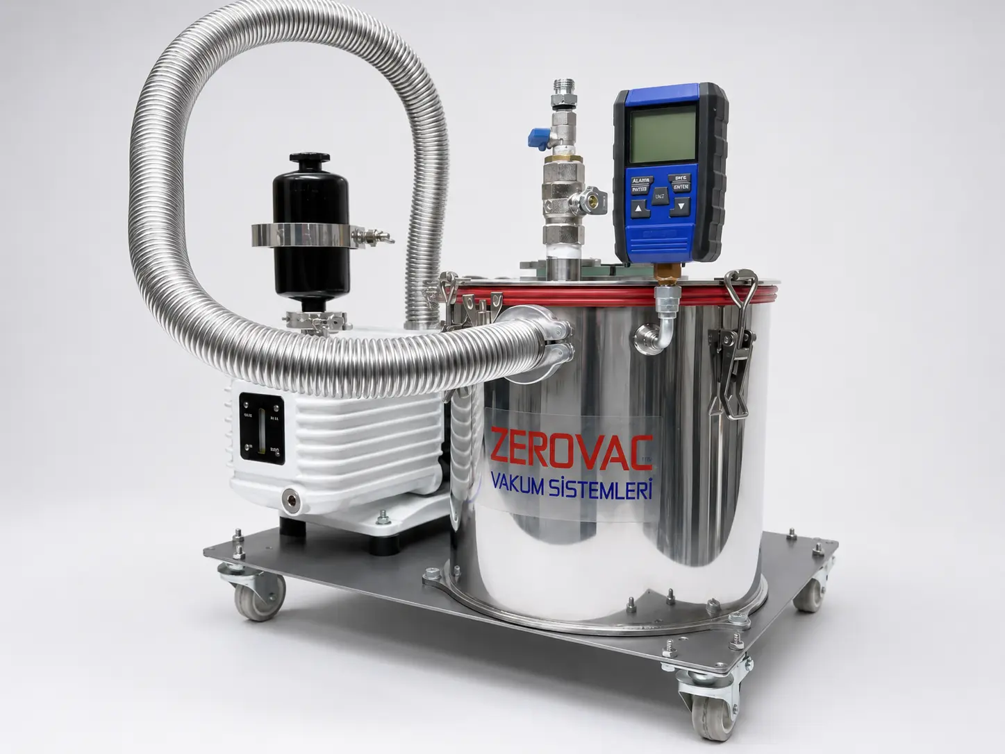
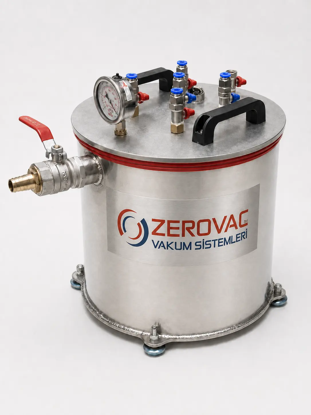
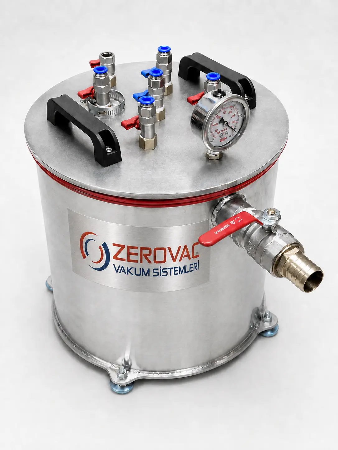
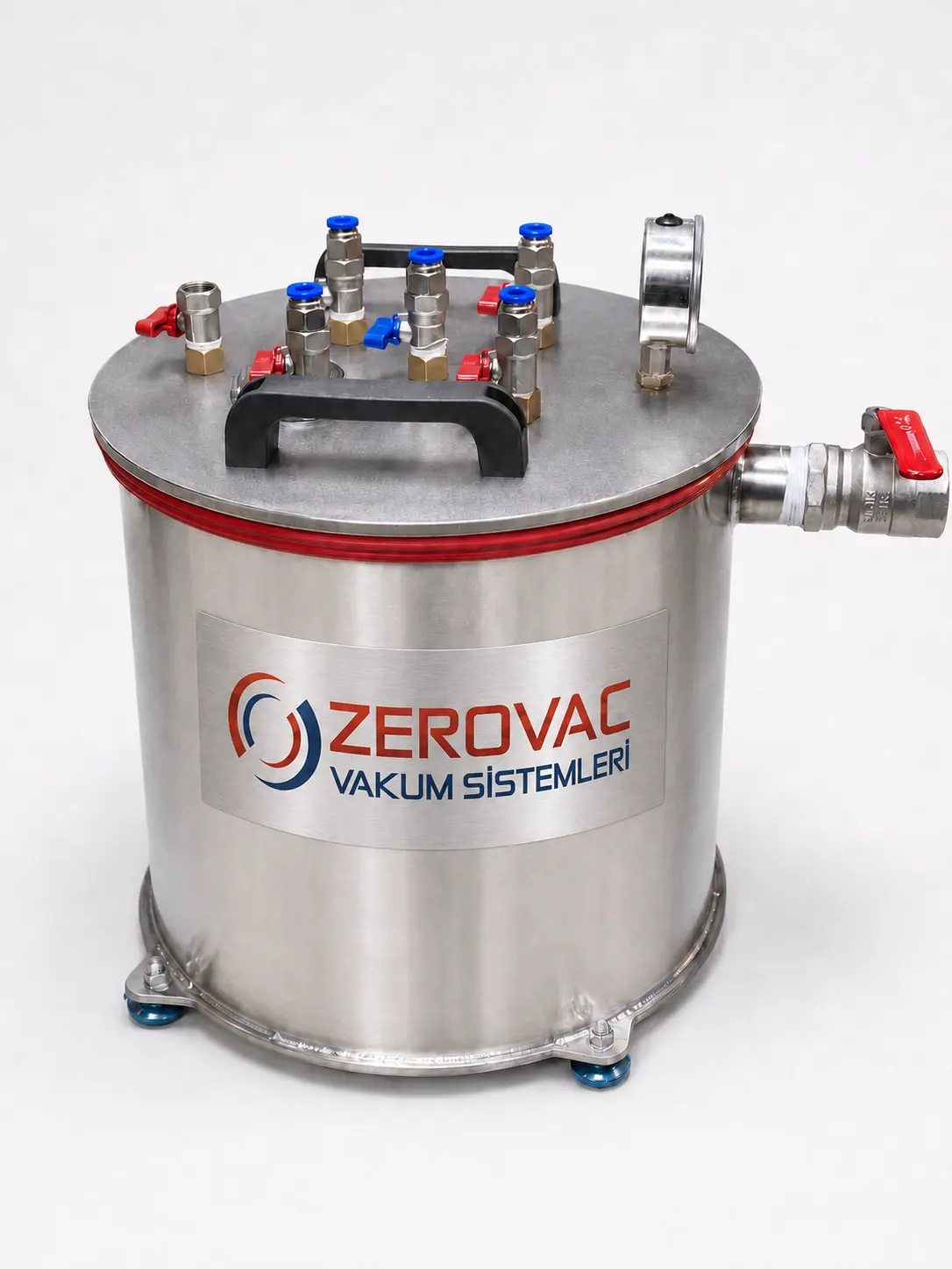
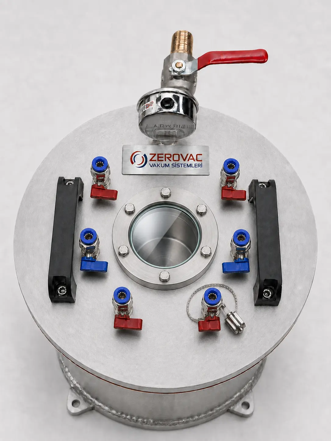
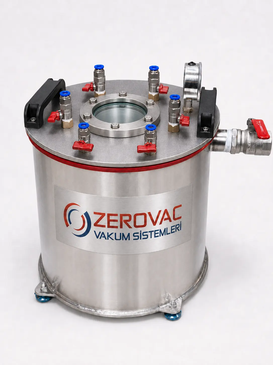
ZEROVAC custom-engineered resin trap

CUSTOM-ENGINEERED SOLUTIONS

Systems developed around the application

Each project is defined by evaluating the target pressure, process conditions, chamber volume and connection requirements as a complete system.

REFERENCE PROJECT 01

Resin Trap

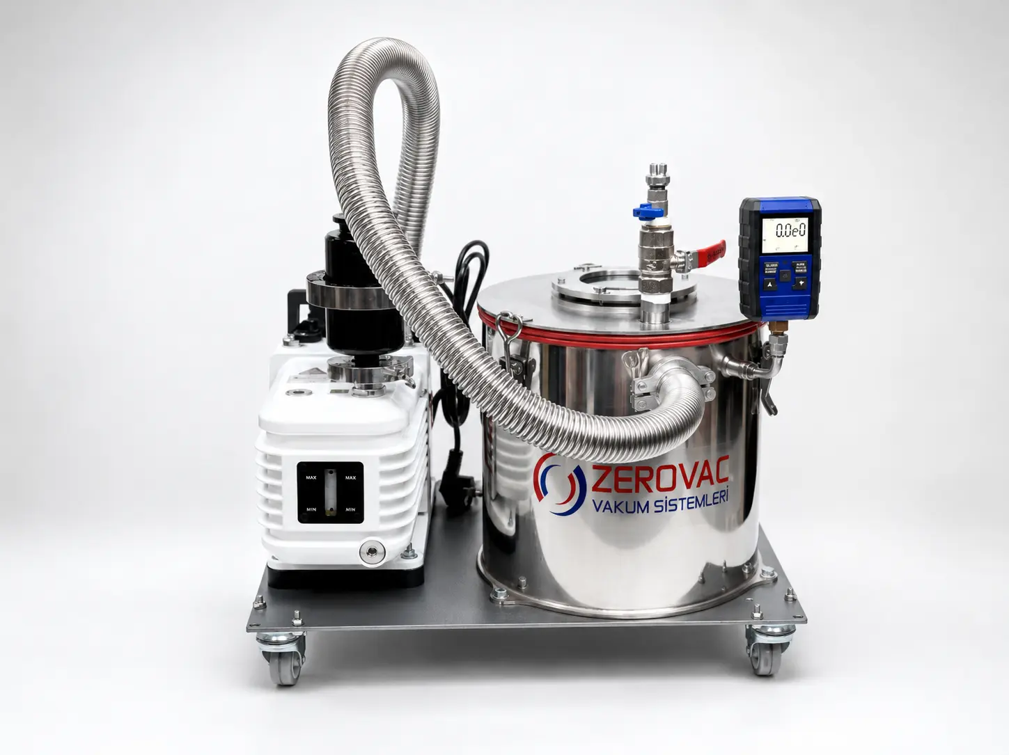
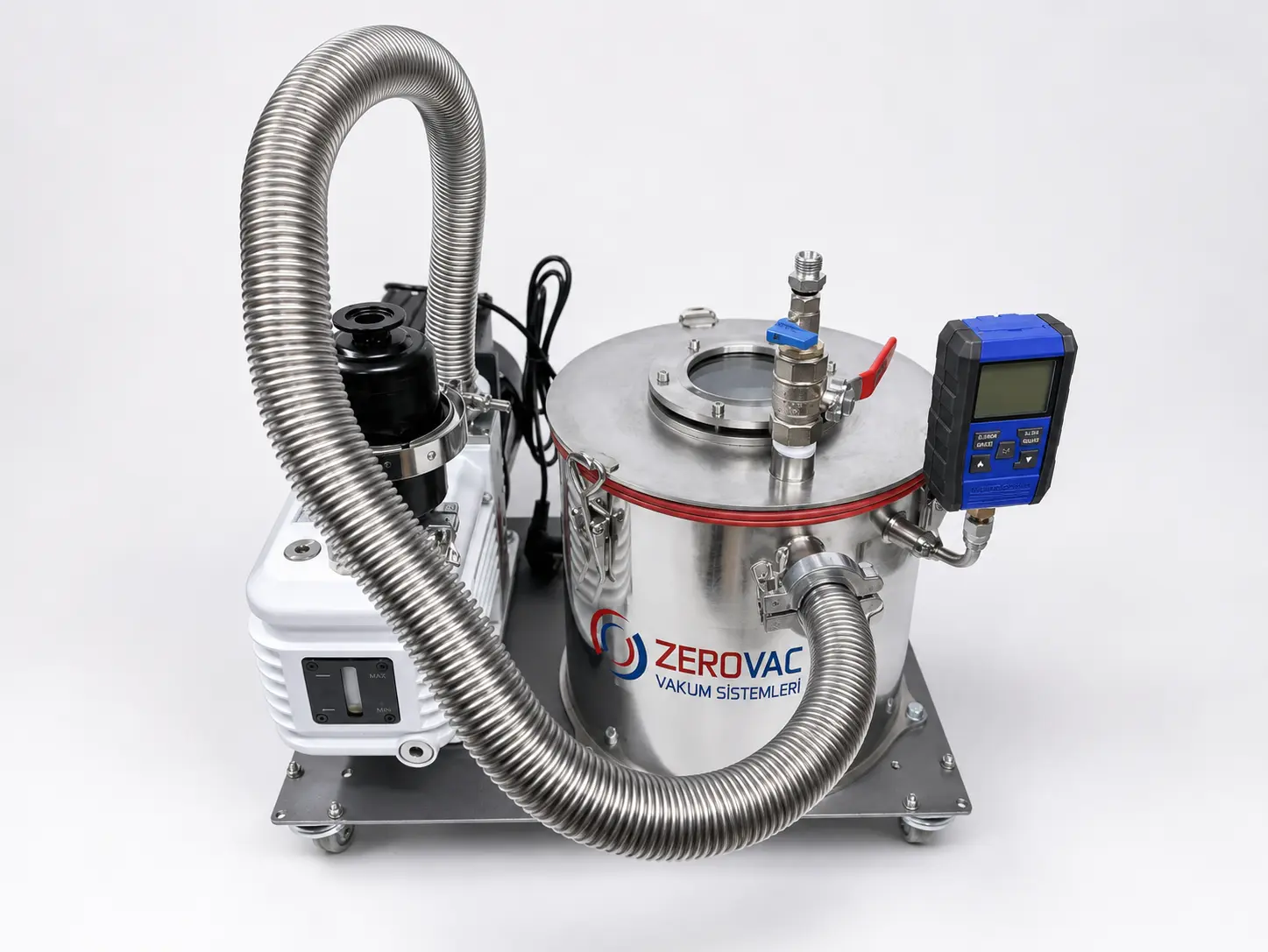
A custom-engineered intermediate vessel that safely captures excess resin during vacuum-infusion processes and protects the vacuum pump.

Vacuum infusionPump protectionCustom manufacture
FUNCTION

Protects the vacuum pump from resin carry-over

The resin trap is installed between the vacuum line and the pump to prevent excess resin from the mould or production line from reaching the vacuum pump. It collects entrained resin and liquid droplets in its own vessel.

This protects the pump from resin contact, keeps the vacuum line clean and supports safer, more efficient system operation. Multiple connection points can be configured to suit different vacuum-line arrangements.
APPLICATIONS

Industrial applications

  • Vacuum-infusion processes in yacht and boat production
  • Carbon-fibre and composite-component manufacturing
  • Laboratories and chemical plants
  • Technical processes where the vacuum line must remain clean

REFERENCE PROJECT 02

Vertical High-Vacuum Chamber

An integrated chamber, pumping package and instrumentation platform for plasma, coating, testing and R&D processes that require a controlled low-pressure environment.

Engineered for the target pressureVacuum instrumentation integrationPump and vacuum-line integration
TECHNICAL SPECIFICATIONS

Vertical high-vacuum chamber

Chamber dimensions320 × 300 mm
Chamber typeVertical cylindrical vacuum chamber
Chamber materialAISI 304 stainless-steel body transparent acrylic lid
Vacuum level≈ 1.33 × 10⁻³ mbar
Chamber sealL-profile gasket
Vacuum portNW40
Vent port1.0″ NPT
Vacuum-gauge port1/4″ NPT
Leak rate≈ 1.01 × 10⁻⁸ mbar·L/s (helium)
FUNCTION

Creates a controlled and repeatable vacuum environment

High-vacuum chambers are used where the atmospheric gas load must be reduced and the process must run under clean, controlled conditions. Chamber volume, target pressure, process gas, material load and cycle time are evaluated together to define the main system architecture.

In ZEROVAC projects, the chamber, pump technology, vacuum instruments, valves, connection ports, sight glass, line components and support frame are engineered as one system. The final configuration and achievable vacuum level are determined from the actual operating conditions.

APPLICATIONS

Precision manufacturing and research

  • Plasma processing, surface activation and cleaning
  • Thin-film and specialised coating applications
  • R&D laboratories and material testing
  • Electronic, sensor and optical-component development
  • Vacuum degassing, drying and conditioning
  • Analytical instruments and custom test rigs

REFERENCE PROJECT 03

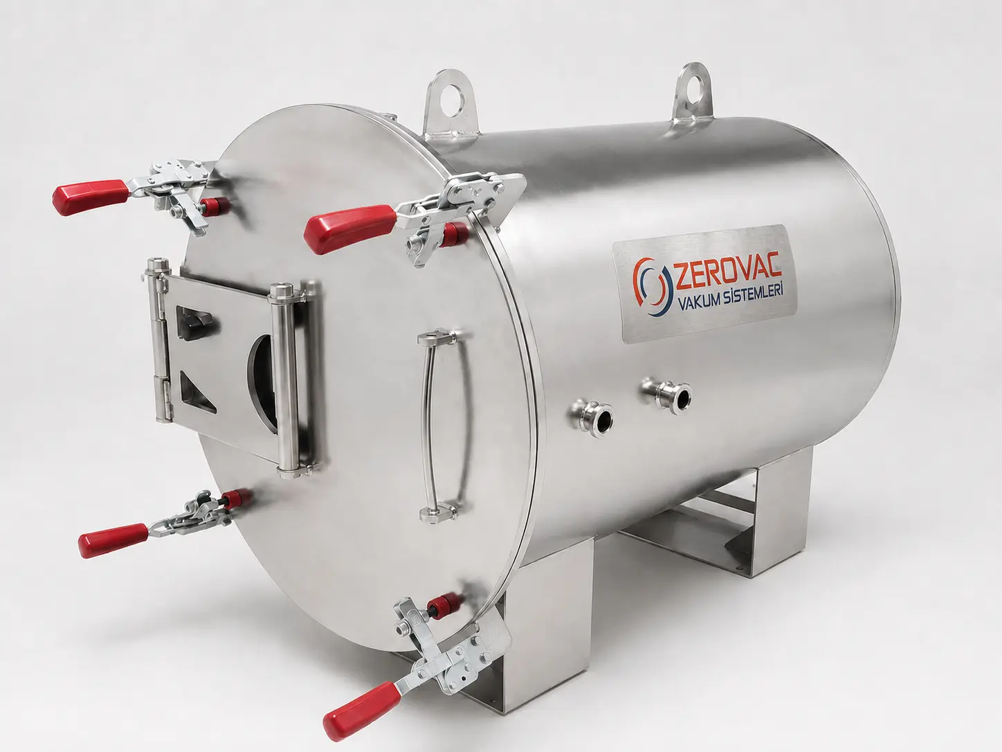
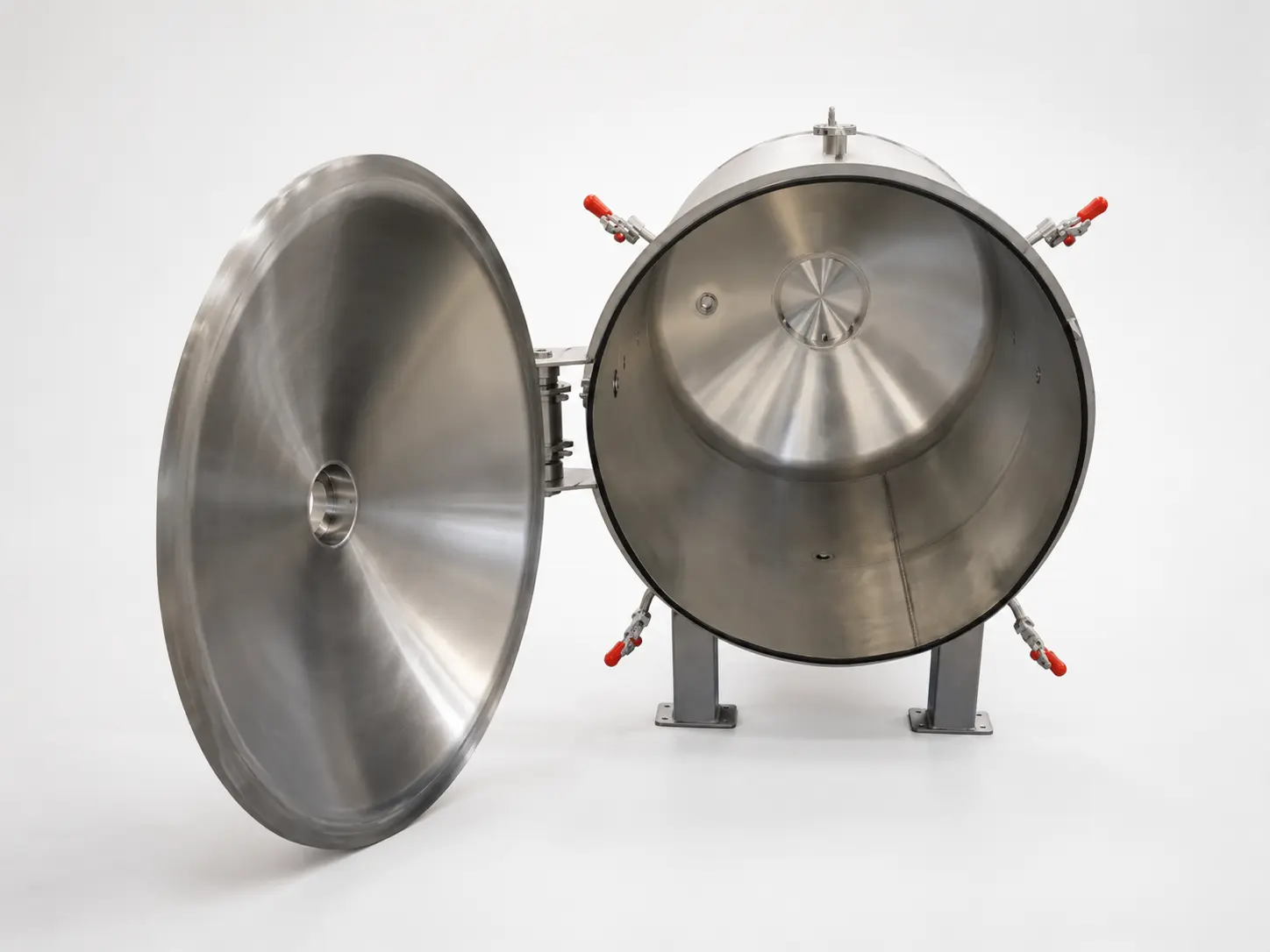
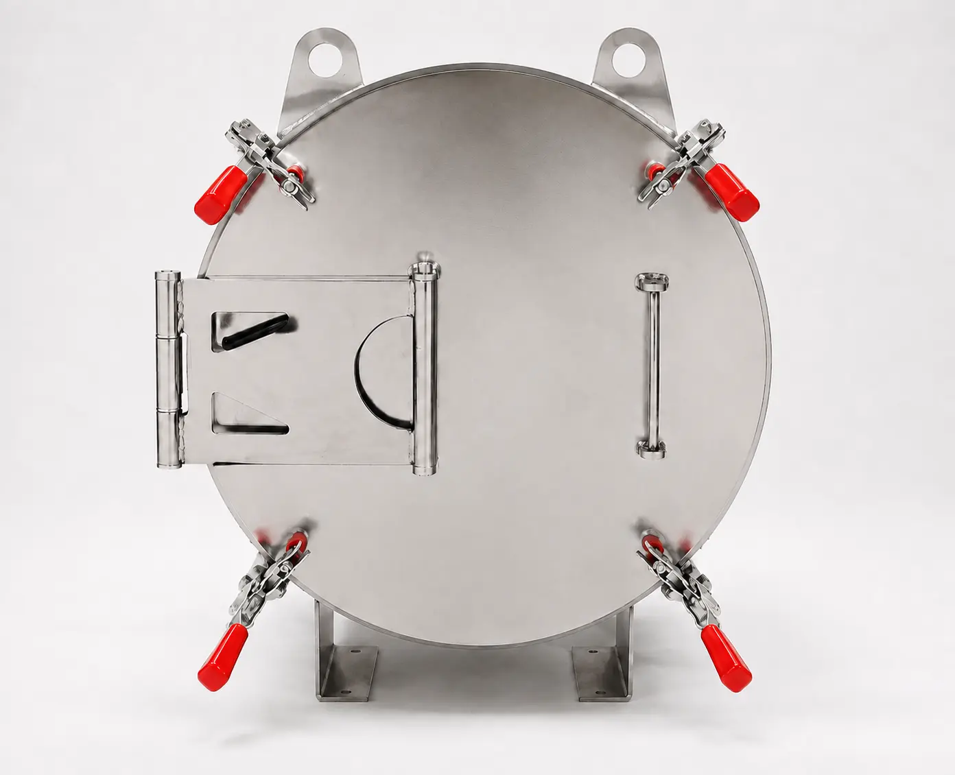
Horizontal High-Vacuum Chamber

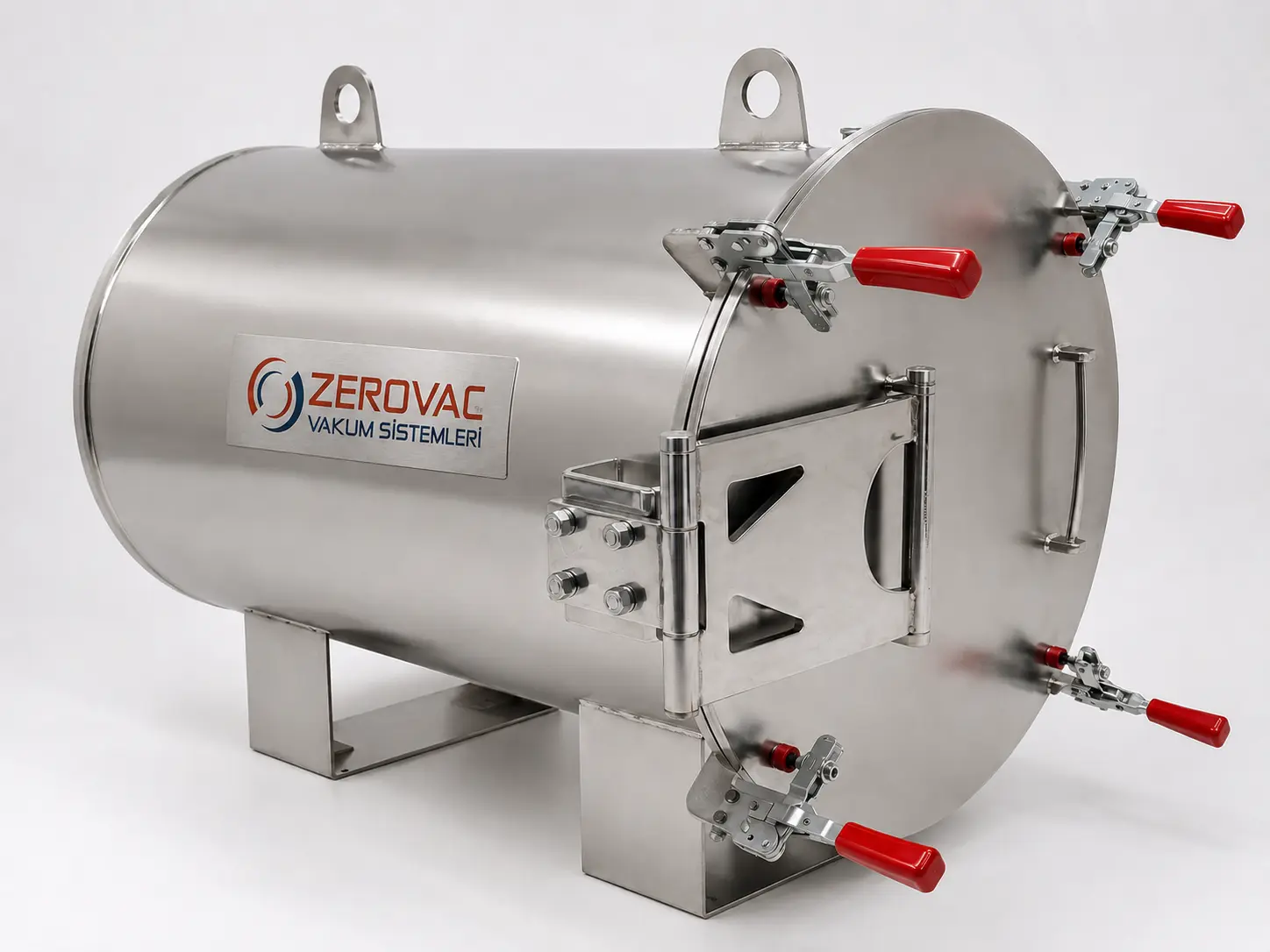
A 143 L horizontal cylindrical vacuum chamber designed for easy loading of larger components, a controlled process environment and integration of different vacuum equipment within one system.

143 L volumeAISI 304 stainless steelMultiple vacuum ports
TECHNICAL SPECIFICATIONS

Horizontal high-vacuum chamber

Chamber dimensionsØ450 × 900 mm
Chamber typeHorizontal cylindrical high-vacuum chamber
Approximate volume143 L
Vacuum level≈ 1.33 × 10⁻⁶ mbar
Chamber / lid materialAISI 304 stainless steel
Lid mechanismButterfly-type, double-acting hinged lid mechanism
SealViton L-profile gasket
Surface finishGlass-bead blasting on the internal and external surfaces
Connection portsNW16 NW25 NW40 NW50 ISO100 ISO200
Leak rate≈ 1.01 × 10⁻⁸ mbar·L/s (helium)
FUNCTION

Provides an accessible vacuum volume for larger components

The horizontal cylindrical design allows bulky components to be placed in and removed from the chamber easily. Its hinged lid mechanism supports safe, practical operation during repeated production and test cycles.

The AISI 304 stainless-steel body, Viton L-profile gasket and connection ports in multiple sizes allow the pumping, measurement, venting and process equipment to be configured around the application.

APPLICATIONS

Manufacturing, testing and R&D

  • Surface coating, plasma and material-conditioning processes
  • Vacuum drying and degassing applications
  • Leak testing of components and assemblies
  • Electronic, optical and precision-component manufacturing
  • Laboratory, R&D and custom experimental systems

REFERENCE PROJECT 04

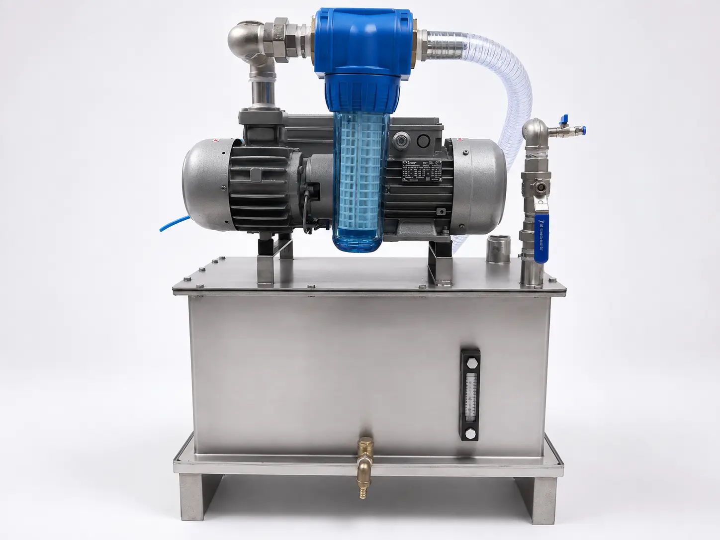
Vacuum System with Liquid Separator

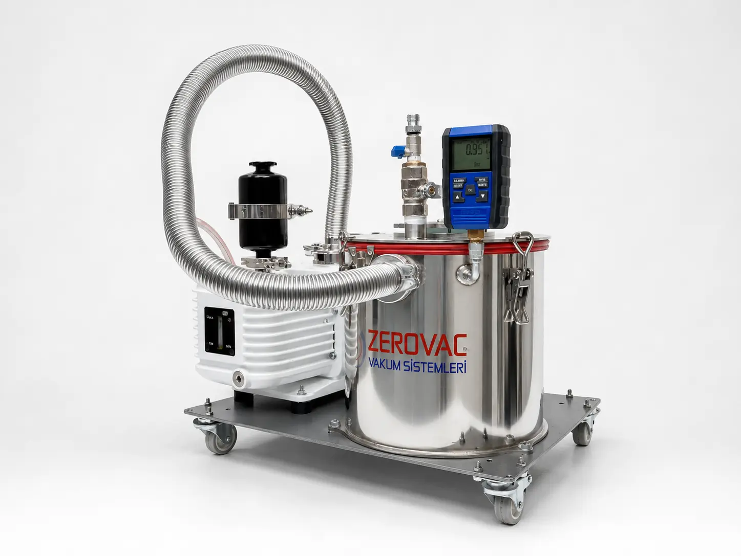
A compact vacuum unit developed to separate non-aggressive liquids carried into the vacuum line from air, collect them and discharge them under controlled conditions in glass, stone and similar machining equipment.

Cyclonic liquid separationAutomatic drainageCompact system
FUNCTION

Protects the vacuum pump from process liquids

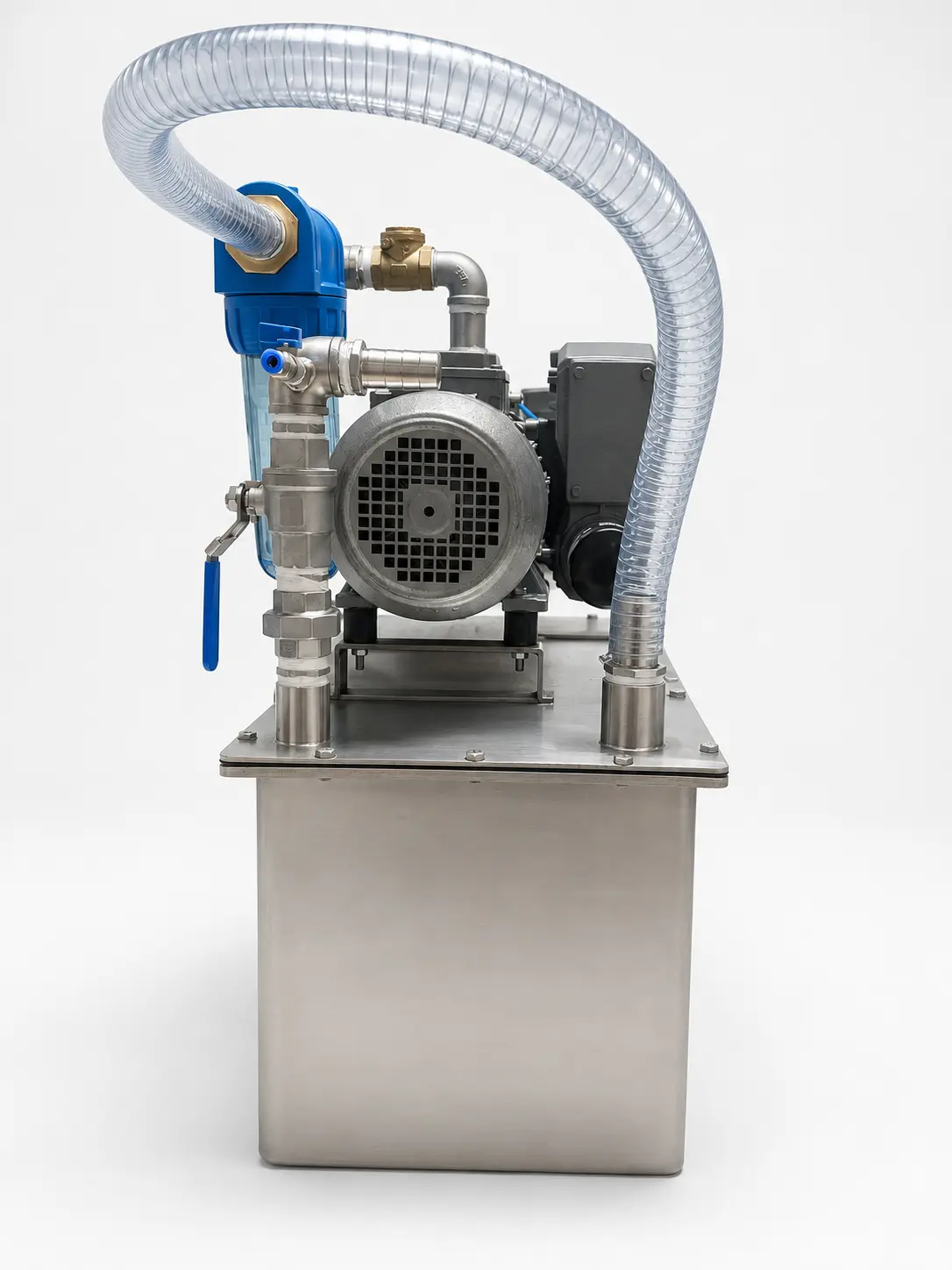
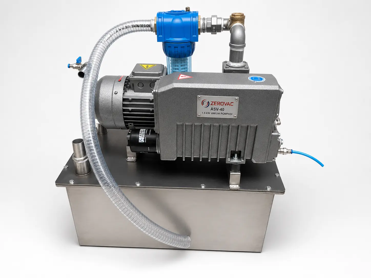
The system is designed for glass and stone machining equipment, as well as applications where non-aggressive cutting or cooling liquid may be carried into the vacuum line. The compact unit connects to the machine through a flexible hose. A ball valve at the vessel inlet allows the unit to be isolated safely during maintenance.

Air and liquid are first separated by the cyclonic arrangement inside the vessel. An external float-level indicator allows the liquid level to be checked visually; when the vessel is full, a level sensor generates an electrical signal and the collected liquid is discharged through an automatic drain valve.

Air that has been freed of droplets but still contains moisture then passes through a condensate-separator filter. A vacuum gauge on the filter indicates operating condition, while an air-admission valve supports controlled drainage of accumulated liquid. An auxiliary non-return valve and gas-ballast arrangement help reduce condensation and carry residual moisture vapour through the pump.

APPLICATIONS

Processes with liquid carry-over risk

  • Glass cutting, drilling and edge-processing machines
  • Marble and natural-stone processing machines
  • Machine tools that use cutting or cooling liquids
  • Processes where non-aggressive liquids may enter the vacuum line
  • Custom machinery requiring liquid retention and automatic drainage

REFERENCE PROJECT 05

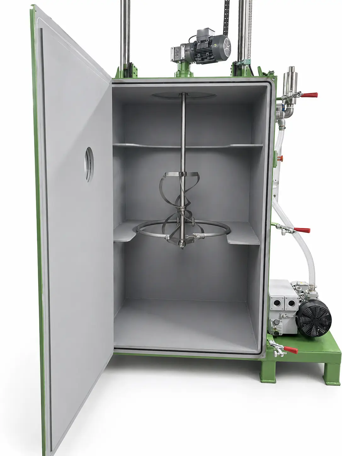
Vacuum Drum Mixing System

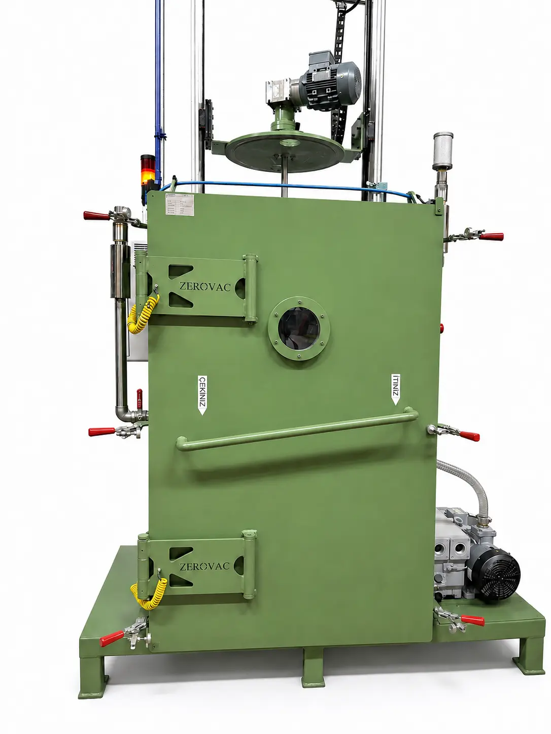
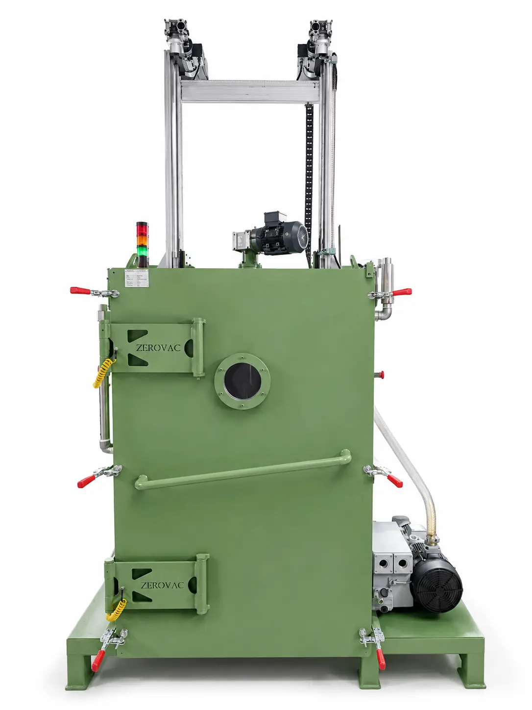
A custom system with a 1,200 L chamber, designed to mix liquids and viscous products in their drums under controlled vacuum and help remove entrained air and gases from the mixture.

1,200 L chamber volume65 m³/h pump0.5 mbar ultimate vacuum
TECHNICAL SPECIFICATIONS

Vacuum drum mixing system

System typeVacuum drum mixing system
Chamber volume1,200 L
Vacuum pumping speed65 m³/h
Ultimate vacuum0.5 mbar
FUNCTION

Mixes drum contents under vacuum and supports degassing

The drum is placed directly inside the vacuum chamber, allowing the product to be mixed under controlled low pressure without transfer to a separate process vessel. The top-driven mixing assembly is lowered into the product; mixing begins after the door is closed and the chamber is evacuated.

Combining vacuum and mixing in one system helps limit air entrainment during processing and remove trapped gases from the product. This supports safer operation and a more consistent, repeatable mix where air bubbles are undesirable.

The 1,200 L chamber provides working space for the drum and mixing assembly. The 65 m³/h vacuum pump supports a specified ultimate vacuum of 0.5 mbar.

APPLICATIONS

Mixtures requiring air and gas removal

  • Resin, epoxy and composite-material mixtures
  • Adhesives, mastics and sealants
  • Paint, pigment and ink preparation
  • Chemical and technical-liquid formulations
  • Custom processes requiring vacuum degassing in a drum
LET'S ENGINEER YOUR SYSTEM TOGETHER

Let's develop the vacuum chamber, vessel or integrated system your process requires.

Share your process, target pressure, working volume and connection requirements so we can define a purpose-built solution.

Discuss Your Project