
Centralised equipment
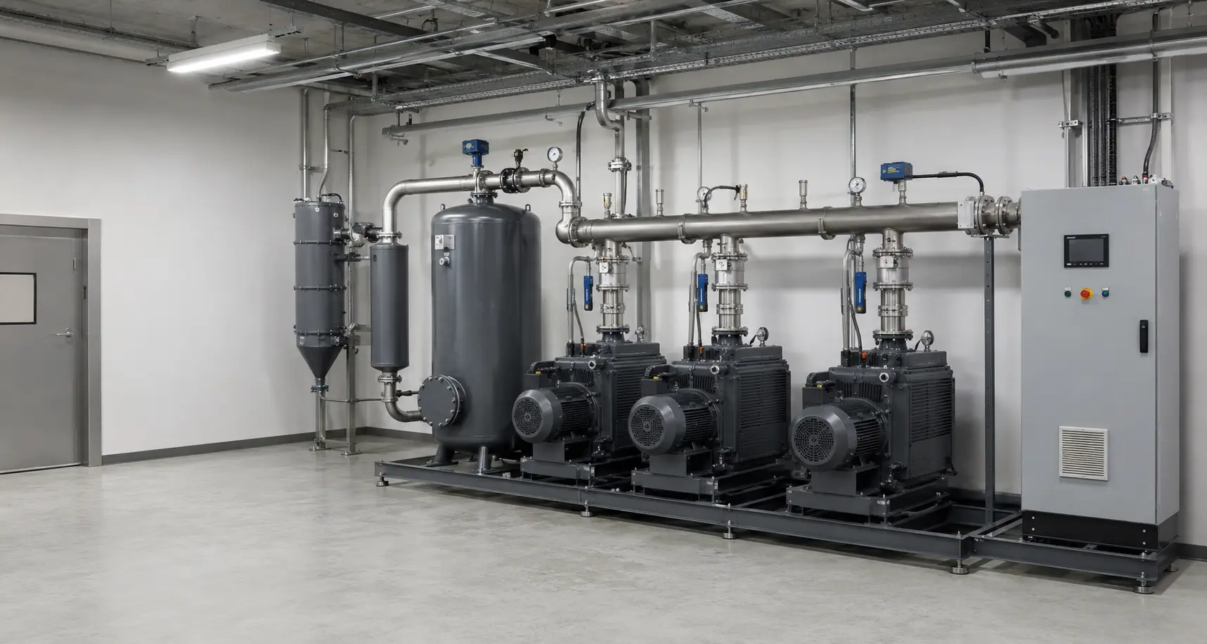
Pumps can be grouped in a service area, improving access and reducing equipment beside production machines.
APPLICATIONS · CENTRAL VACUUM
A central station is engineered around simultaneous demand, vacuum zones, network pressure loss, duty/standby philosophy and the operating pattern of every connected machine.
Adding the nameplate capacities of all machines usually overstates demand, while ignoring simultaneous use and network loss risks undersizing. A central system uses a load profile and hydraulic network calculation.
Pumps can be grouped in a service area, improving access and reducing equipment beside production machines.
Multiple pump modules can stage on and off as plant demand changes.
Redundancy and automatic sequencing can be configured around the required availability.
Different pressure levels and consumer groups can be separated into controlled distribution zones.
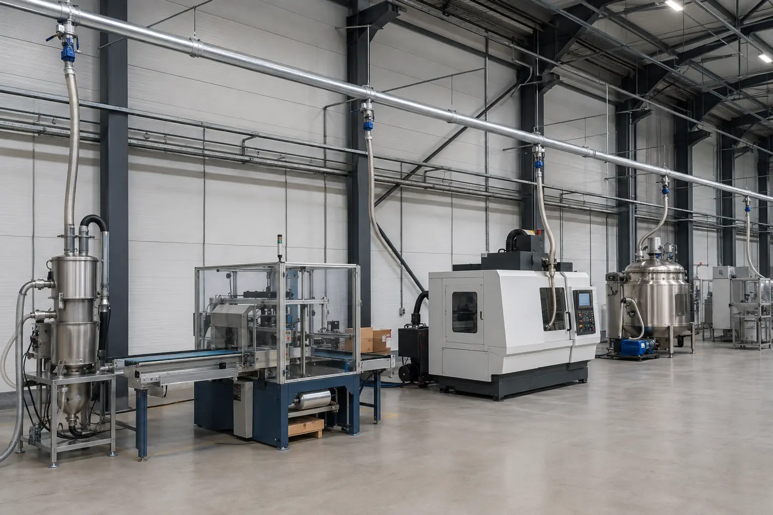
Main diameter, branch sizing, distance, fittings, isolation and receiver volume all influence pressure at the point of use.
Four data groups define generation, storage, distribution and control.
Talk to Our Technical TeamList each machine's pressure, capacity, cycle time and connection size.
Define which consumers can operate together and how demand changes by shift or production mode.
Provide pipe lengths, elevations, proposed zones and the furthest or most critical consumers.
Set duty/standby philosophy, receiver capacity, sequencing, alarms and maintenance isolation.
One or more pump families may be used when the plant contains different vacuum levels or gas conditions.
Published family ranges are indicative. Final selection must be checked at the actual operating pressure, gas or material load, temperature, duty cycle and installation conditions.
Reliable performance depends on the pump or blower, protection equipment, line arrangement, controls and the real process operating point.
Capacity and pressure are checked together at the actual inlet conditions and duty cycle.
Share Operating DataFilters, separators, condensers, receivers and valves are selected around moisture, particles, liquid carry-over and process risk.
Review the Process LoadPipework, controls, isolation, accessibility and redundancy are included in the final system architecture.
Explore Vacuum TechnologiesSend each machine's vacuum requirement, cycle, simultaneity, network layout, zoning and redundancy expectations so we can define the central station.