
Closed-line transfer
Suitable granules, powders and lightweight materials are conveyed through enclosed piping.
APPLICATIONS · PNEUMATIC CONVEYING
Vacuum or pressure conveying systems are sized from material behaviour, required throughput, conveying distance, lift, bends, filtration and total pressure loss.
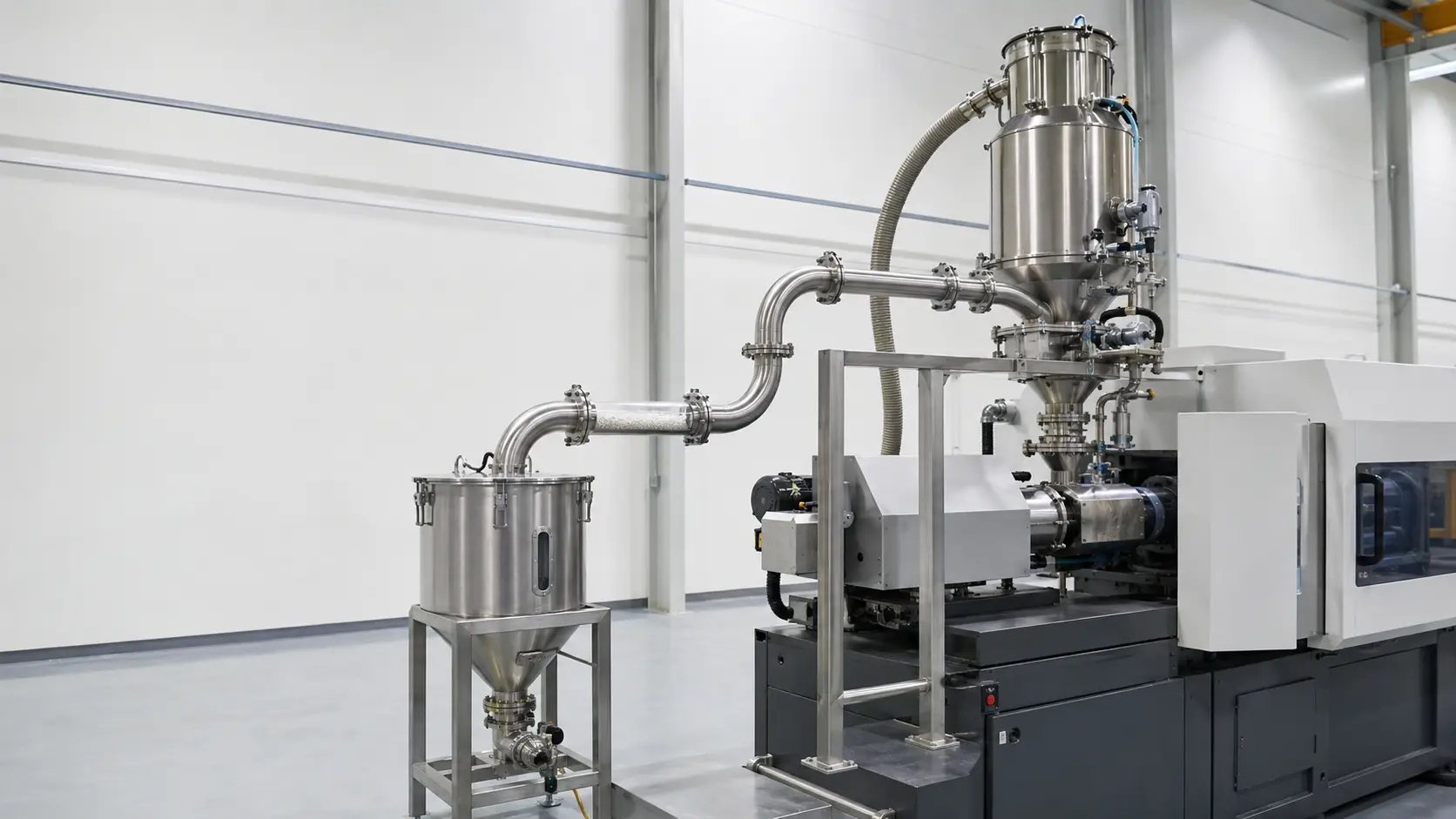
Bulk density, particle size, moisture, fragility and flow behaviour change the required air velocity and pressure difference. Blower selection follows the complete line calculation.
Suitable granules, powders and lightweight materials are conveyed through enclosed piping.
Receivers, rotary valves and filters can be arranged around the plant layout and process sequence.
Airflow is selected to move the material while limiting blockage, attrition and unnecessary energy use.
One blower may serve a dedicated machine or a controlled multi-point conveying network.
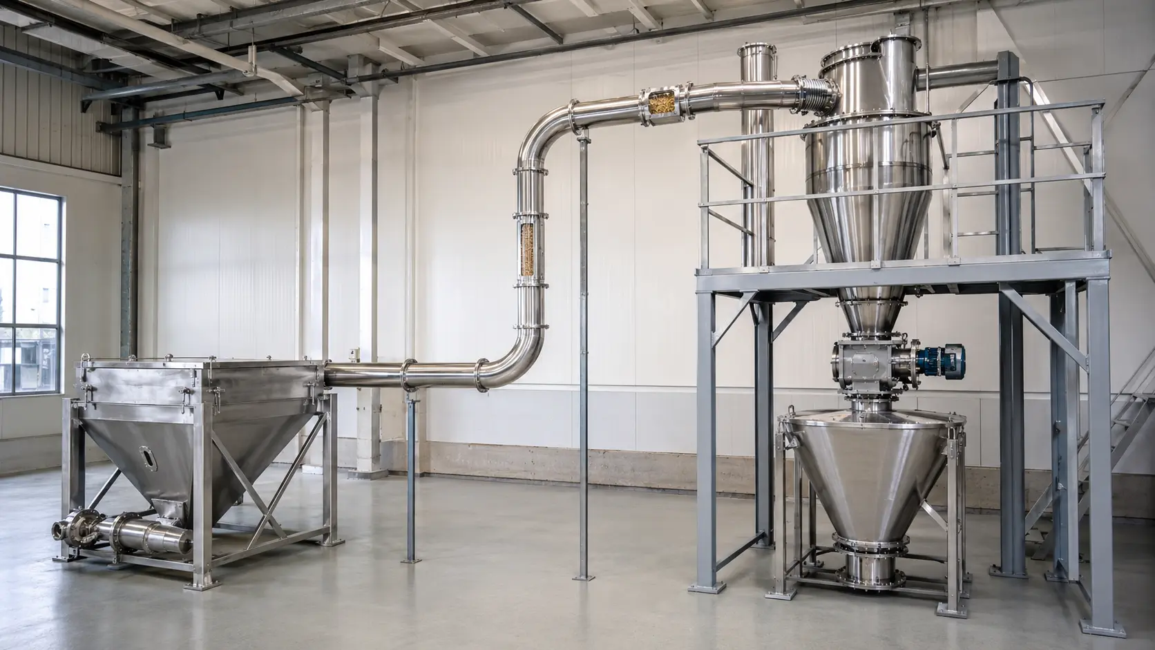
Pipe diameter, horizontal and vertical distance, bends, filters, receivers and discharge equipment are included in the operating-point calculation.
Four information groups define the conveying duty.
Talk to Our Technical TeamProvide bulk density, particle size, moisture, temperature, fragility and flow behaviour.
Define mass flow, batch size, conveying time and the expected operating schedule.
Include pipe diameter, total length, vertical lift, bends and flexible sections.
Filter area, cleaning method, rotary valve and discharge arrangement affect system resistance.
The final model is selected at the calculated operating point, not from free-air capacity alone.
Published family ranges are indicative. Final selection must be checked at the actual operating pressure, gas or material load, temperature, duty cycle and installation conditions.
Reliable performance depends on the pump or blower, protection equipment, line arrangement, controls and the real process operating point.
Capacity and pressure are checked together at the actual inlet conditions and duty cycle.
Share Operating DataFilters, separators, condensers, receivers and valves are selected around moisture, particles, liquid carry-over and process risk.
Review the Process LoadPipework, controls, isolation, accessibility and redundancy are included in the final system architecture.
Explore ZRV BlowersSend material properties, throughput, pipe diameter, horizontal and vertical distance, bends, receiver, filtration and duty cycle for a system review.